
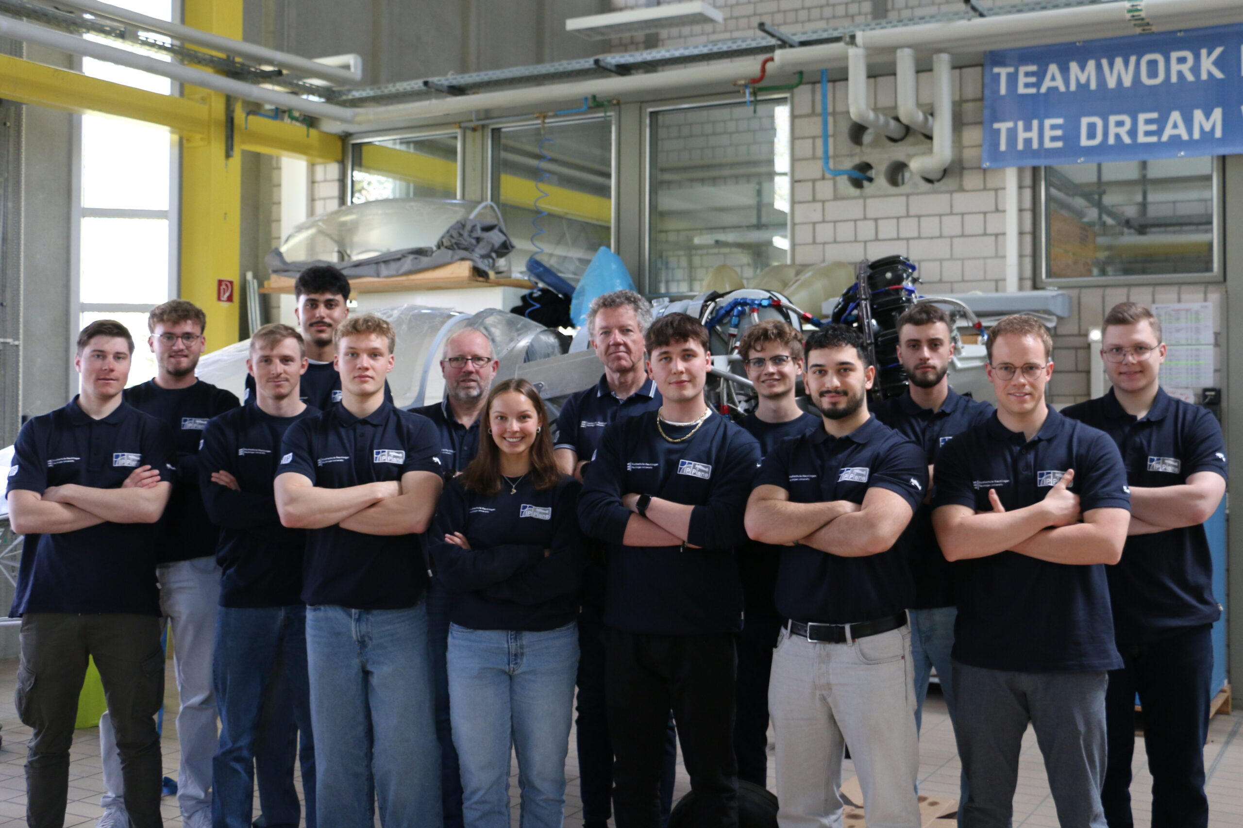
As the summer semester of 2026 comes to a close, the IP Plane team can look back on a period shaped by technical problem-solving, consistent quality standards and strong collaboration.
Building on the work and documentation of previous teams, we continued the construction of the Pitts Model 12 and resolved several open issues of the wings, engine and avionics systems.
From the beginning, our goal was not simply to complete as many work packages as possible. Every task had to be carried out responsibly, accurately and with the future safety of the aircraft in mind. This principle guided the team through the planning, execution and close-out phases.
Avionics Construction
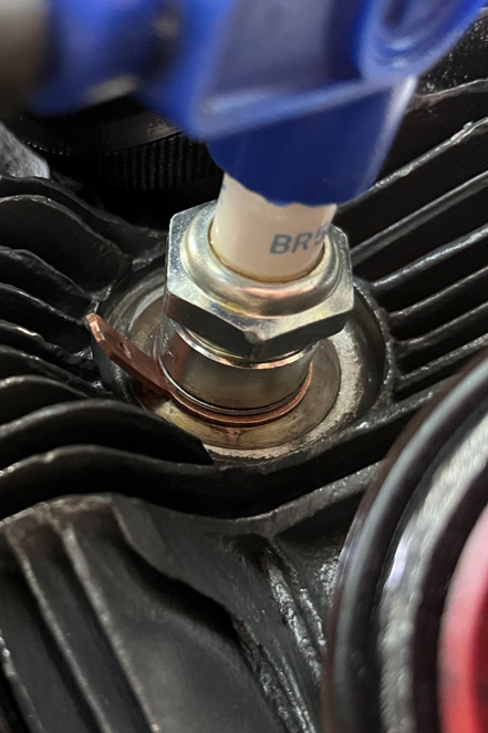
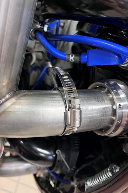
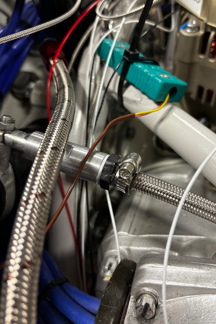
The Avionic Team tested the extensions for the Cylinder Head Temperature and Exhaust Gas Temperature sensors using the required Type K cables and connectors. After the tests confirmed reliable measurements, the CHT sensors were installed underneath the spark plugs of all nine cylinders and the EGT sensors were mounted in the exhaust pipes of cylinders three and eight.
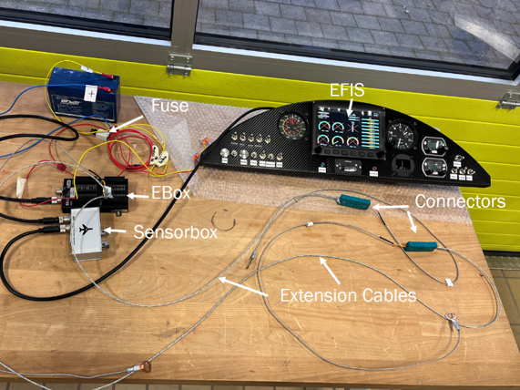
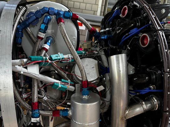
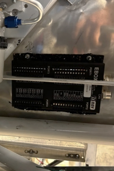
Further work focused on the engine electronics. A custom aluminium fitting was manufactured to connect the MAP sensor to the intake line, while the external voltage regulator and EBox were mounted with vibration protection. The required cables were then routed through the aircraft, labelled and prepared for their final connections. A compact circuit board for the required pull-up and pull-down resistors was also developed.
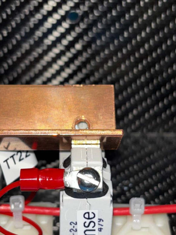
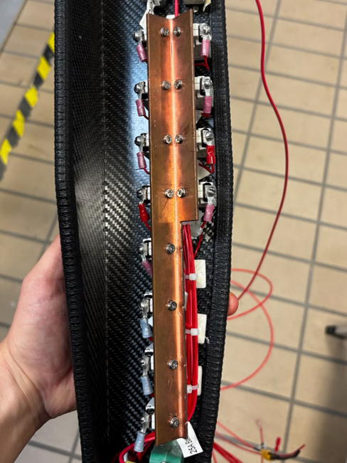
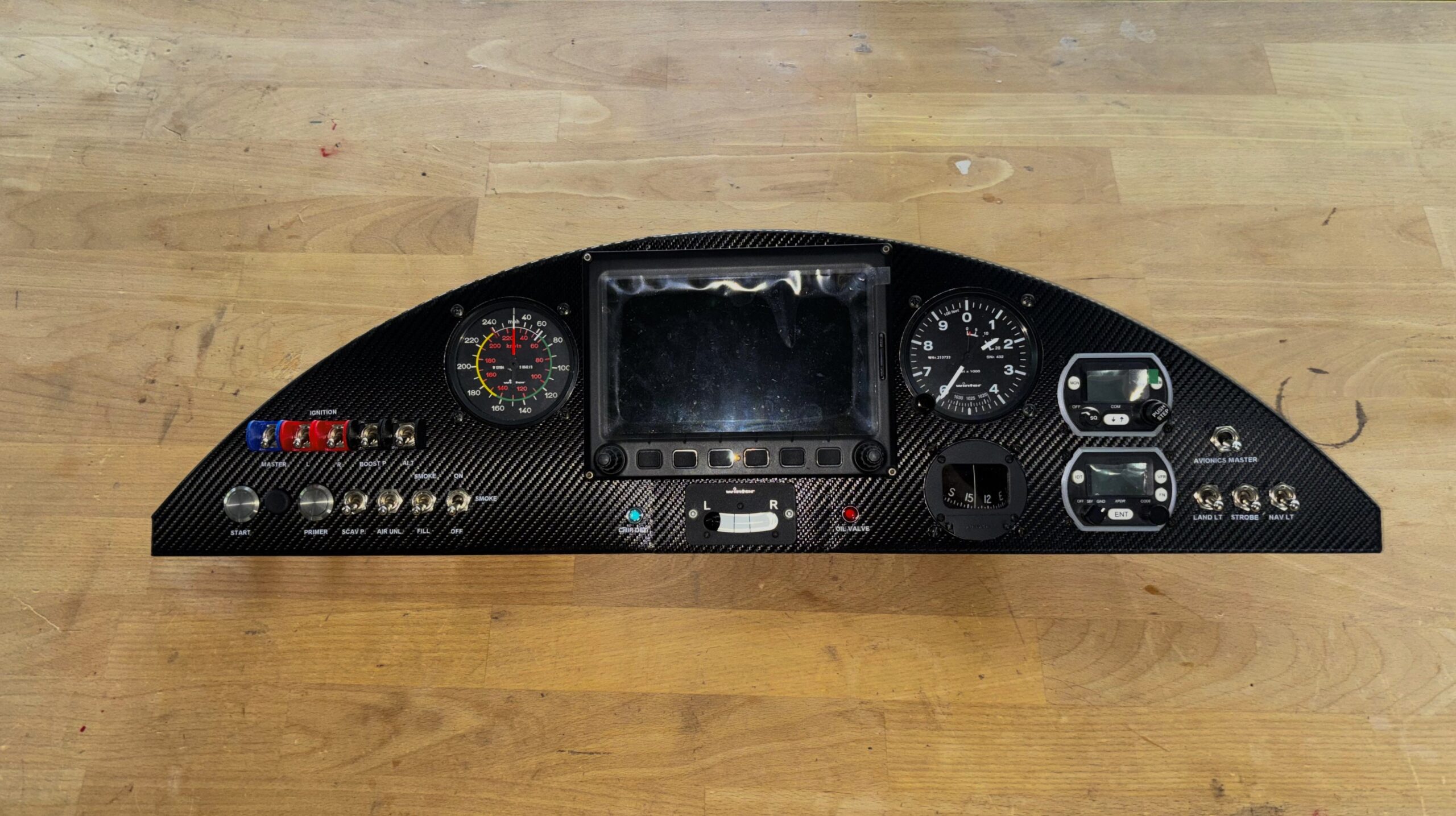
The pilot panel received its final switch layout, clear labelling and protective switch guards for the main controls. The copper distribution bar on the fuse panel was also adjusted to provide correctly aligned and reliable electrical connections.
Engine Construction
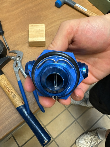
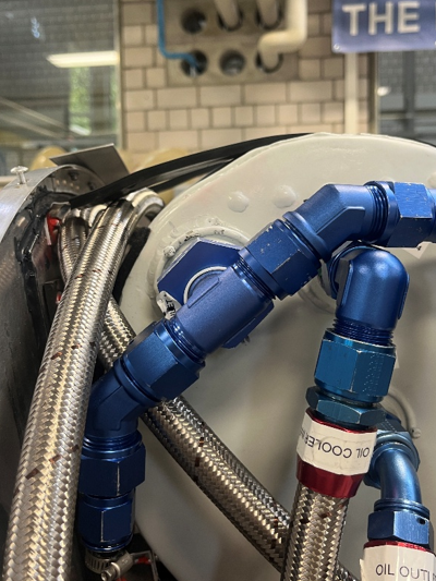
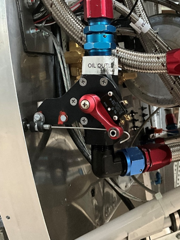
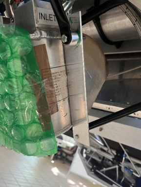
The Engine Team completed the installation and mechanical securing of the oil inlet, thereby finishing an important part of the oil system. The fuel pressure sensor and its connecting line were also installed at the firewall using specially adapted fittings.
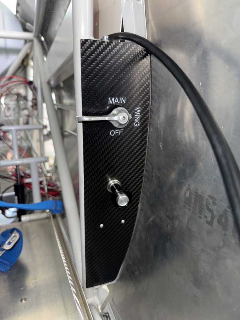
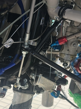
A carbon plate was manufactured and installed in the cockpit as a mounting surface for the mechanical controls. The Bowden cable for the oil shut-off valve was then routed from the cockpit through the firewall and connected to the valve. A separate solution, including a custom aluminium bracket and spacer, enabled the Bowden cable for the carburettor to be installed as well.
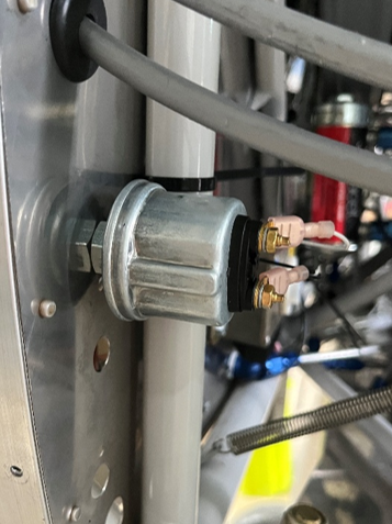
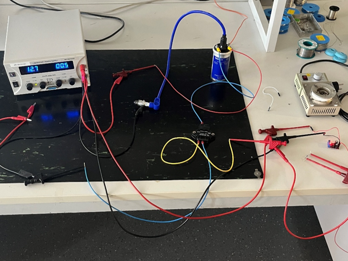
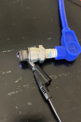
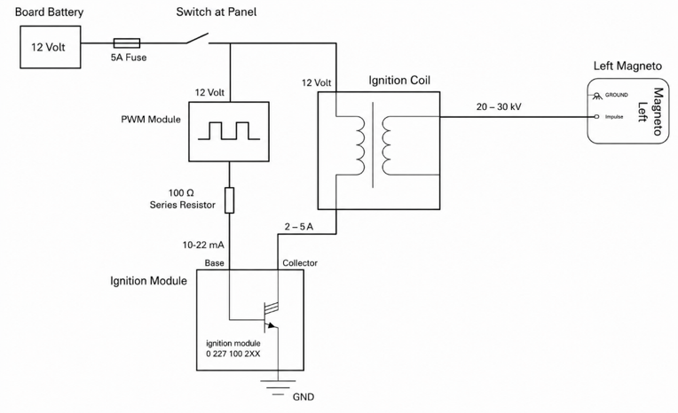
One of the Engine Team’s most important development tasks was the Shower of Sparks Unit for the engine-starting system. The electrical circuit was developed and the required components were assembled and tested with support from the electrical laboratory. During testing, the electrical current remained below 2.5 amperes, confirming that a five-ampere fuse is sufficient for the planned installation.
Wing Construction
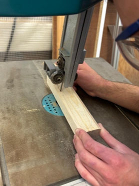
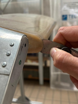
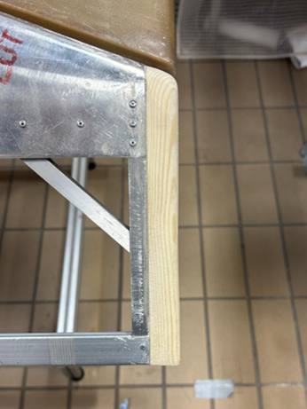
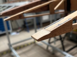
The Wing Team manufactured wooden caps for the outer ends of the ailerons. Based on a self-made template, the components were cut from a wooden block, carefully shaped by hand and continuously checked against the geometry of the ailerons before being bonded and secured in their final positions.
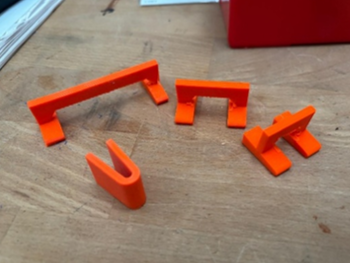
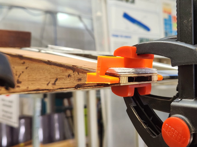
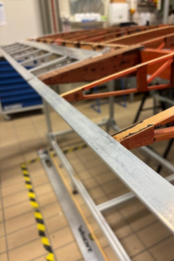
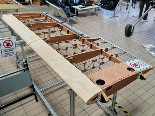
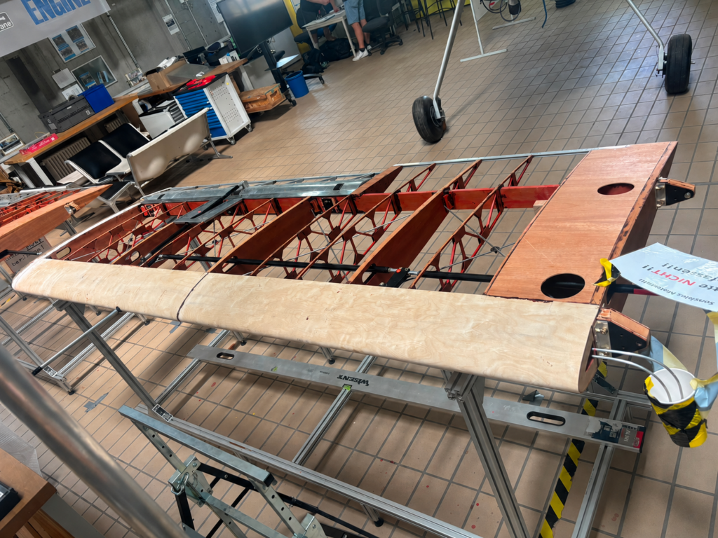
One of the Wing Team’s largest work packages was the installation of the trailing edges. Specially manufactured 3D-printed templates were used to reproduce the required profile and precisely adjust the delicate wooden ribs. Their position was repeatedly checked with the measuring tools to ensure that the trailing edges formed a continuous aerodynamic line with the ailerons.
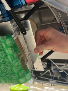
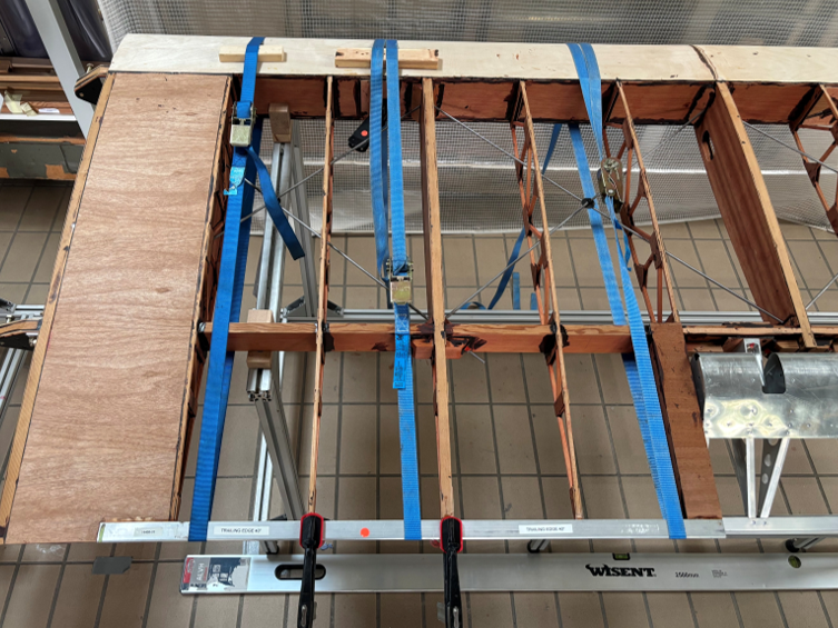
Once the required geometry had been achieved, the trailing edges were aligned and bonded using T88 adhesive. Straps were used to apply even pressure across their complete length during curing.
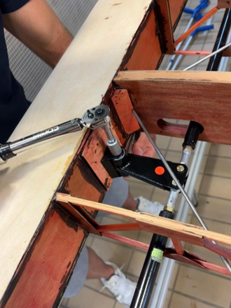
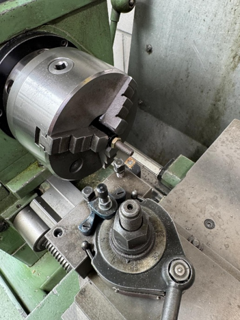
The aileron idlers and bellcranks were installed inside the lower wings. During the subsequent installation of the push tubes, the team identified that the existing geometry restricted the required movement of the ailerons. The threaded sections were therefore shortened and the system was adjusted to provide sufficient range of motion.
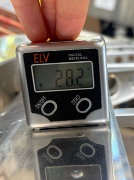
This creates enough adjustment margin for the final installation. Once the wings are mounted on the aircraft and connected to the cockpit controls, the aileron angles can be precisely aligned and fine-tuned to meet the required specifications.
Finally, uneven transitions and adhesive residue were removed before both lower wings were sanded and protected with two coats of varnish. With these final steps completed, both lower wings are now finished from the team’s side and ready for fabric covering.
Reaching this milestone was one of the Wing Team’s main achievements of the semester. The following project phase can now shift its focus to the construction of the upper wings.
Looking Ahead
Together, the three construction teams achieved visible and technically significant progress on the Pitts Model 12. The lower wings were brought close to completion, major parts of the avionics and cockpit systems were installed, and several important engine components were completed.
The remaining tasks and technical decisions have been documented to provide the next IP Plane team with a strong foundation for continuing the project.
Every completed component brings the Pitts Model 12 one step closer to its future first flight.
“I am incredibly proud of what we achieved together this semester. Everyone brought commitment, technical focus and a strong sense of teamwork to the project, even when challenges arose. I am confident that we have created a solid foundation for the next team and taken the Pitts Model 12 another important step closer to completion.”
Diyar Yer, Project Manager Summer Semester 26
